(Yet Another)
Stand Alone WSPR Beacon Project
( Last Update 2012-4-08 )
The
project has been abandoned for now due to lack of time and interest.
This project is a stand alone(no
PC) 2 Watt WSPR beacon designed with the idea to be solar powered
and unattended in remote or mobile location. The following
features
are implemented:
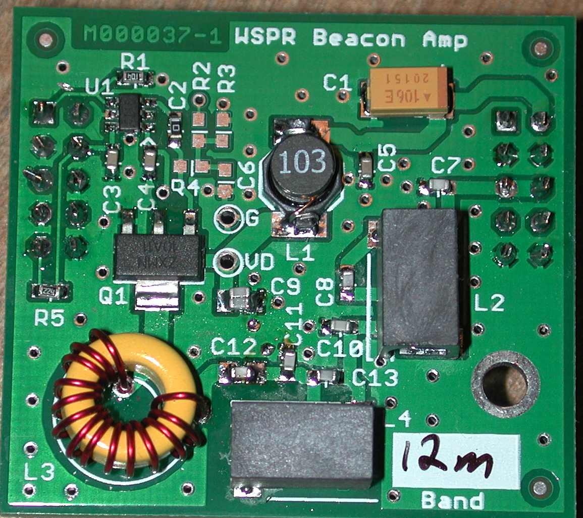
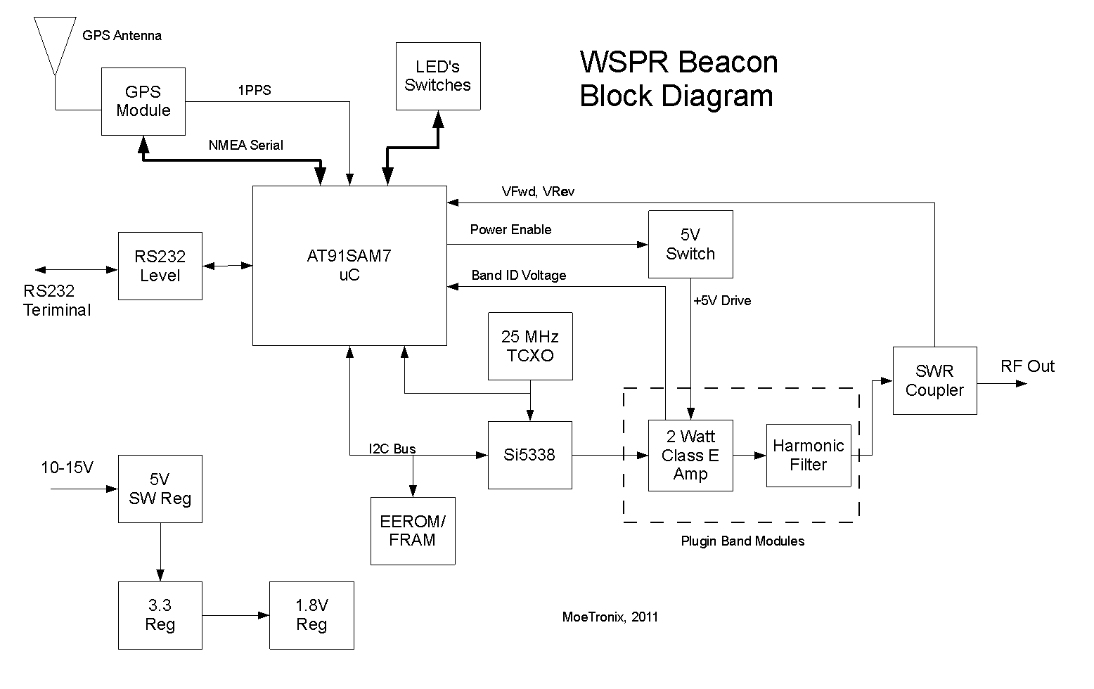
- Plugin Band modules
consisting of a 2 Watt class E amplifier and harmonic filter allow band
change.
- Band modules are
autodetecting so frequency is automatically selected.
- Current bands are 160m
through 10m. Custom Frequency Modules could possibly be made up
to 200MHz.
- Built in GPS receiver for
position and time information.
- TXCO reference to allow
days of operation without GPS signal.
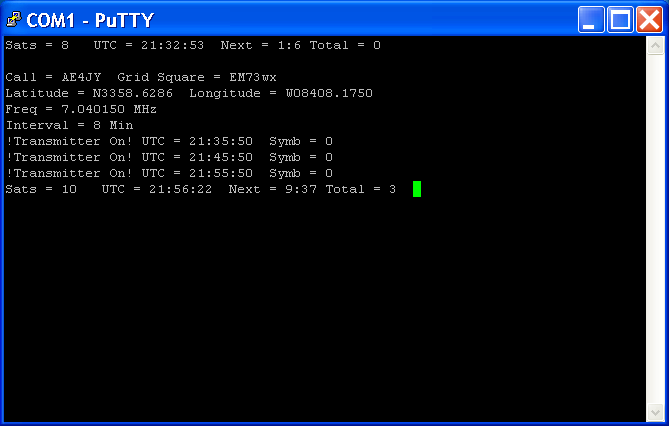
- Setup using RS232 terminal.
- Settings saved in
non-volatile memory.
- Grid Square automatically
created from current GPS location.
- Built in VSWR circuit for
initial tuning and antenna monitoring during operation.
- Various status LED's and
switch for selecting tune mode, setup mode, boot mode, etc.
- Firmware update using
RS232 serial port.
- GPS antenna current
monitor circuit for 5V or 3.3V active antennas.
- Board fits in Hammond
1455J1202 (120 x 78 x 27 mm) enclosure.
Ver 1.01
Preliminary User Manual
Rev 2
WSPR Beacon Schematic
Rev 1 WSPR
Beacon PA Schematic
Rev 1.01 WSPR Beacon Firmware Source Code
Key Components:
Initial Prototype board set:
Band Module
Main
Components
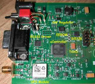
Click on for larger Image
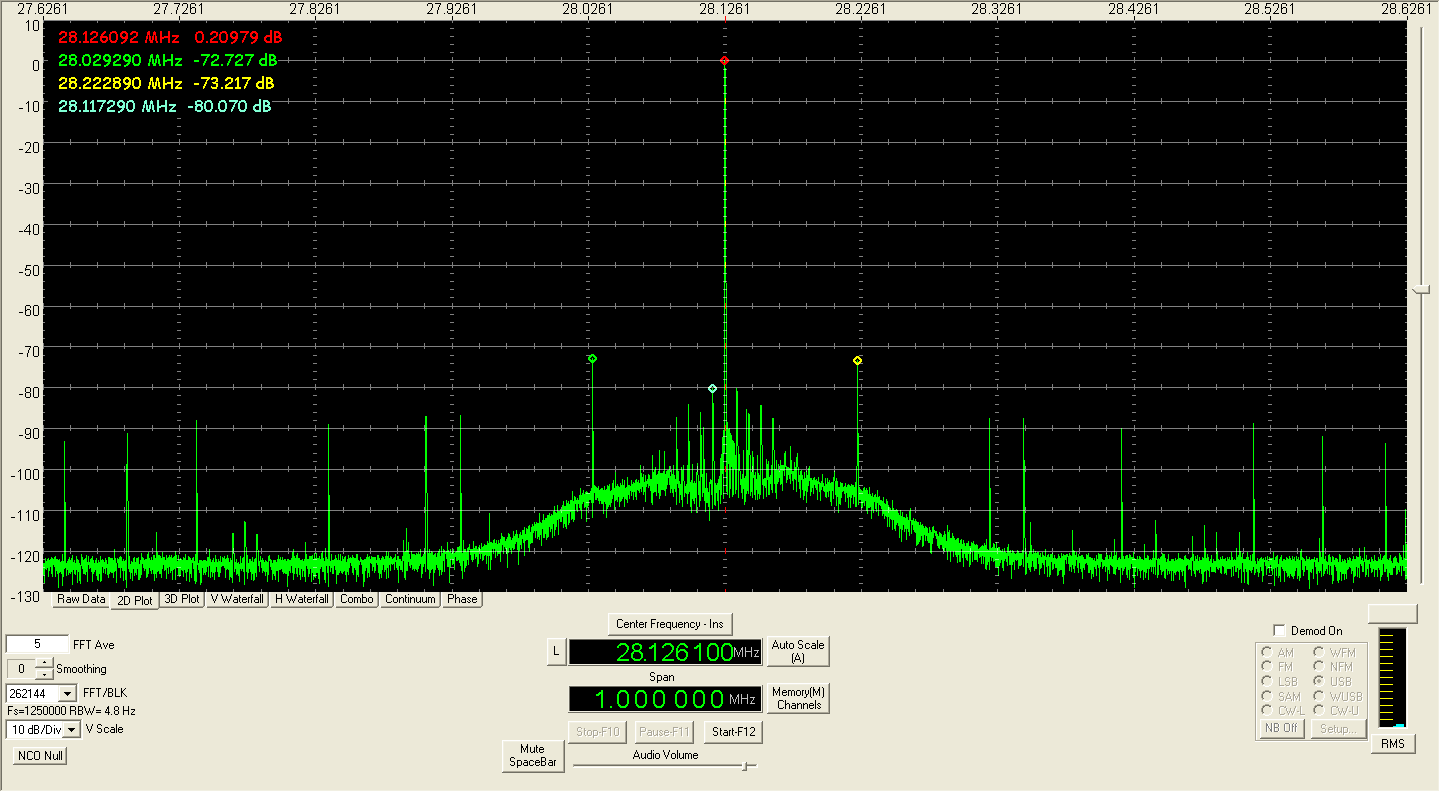
Typical Spurious Output Plot in 1MHz
bandwidth.
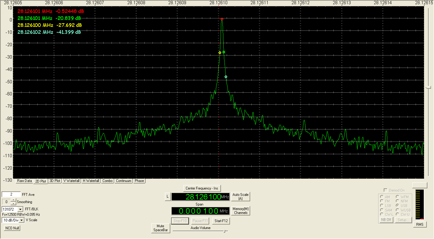
Typical Phase Noise Plot in 100 Hz
bandwidth.
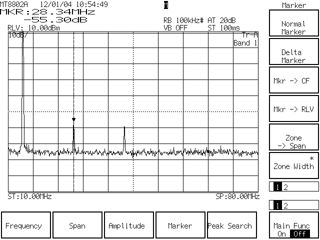
Harmonic Plot of 20m
(Since
LP filter is >60dB, these harmonics may be generated from inline
coupler diodes or coupled from the module connector power pin)
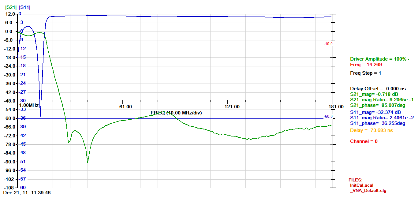
 Harmonic Filter
Sweep
RS232 Serial Terminal Session
Overnight Testing Beacon on 20m with
Vertical Attached to Deck
Click on for larger image
Current
Status:
- Fully
functional prototype from 40m to 10m.
- 160m
and 80m PA modules awaiting different filter inductors.
- Second
unit is built so another tester can evaluate.
Issues:
- No
way to power down the Si5338 chip so it is drawing ~50mA when not
transmitting.
- High
VSWR while tuning sometimes gets the GPS module in a state where it
doesn't output the 1PPS.
- 160m
and 80m filter needs higher Q inductors not obtainable with SMT parts
or perhaps less filtering.
- Due
to toroid use, manufacture of this board would be too expensive for
hobbists.
- Due
to very small SMT components , hand building is very tedious so not
very useful as a kit.
Next
Steps:
- Find
proper filter inductors for 80m and 160m. May have to be toroids.
- Consider
new pcb with minor changes such as a means to power down the Si5338 and
monitor input voltage.
- Document
design, drink a beer and move on the the next idea.


